1970’s Motorcycle Refit
Market:
Parts Aftermarket for British Motorcycles

Competencies:
Mechanical Design
Embedded Controller Hardware Design
Embedded Firmware Design
Programmable Logic Design
PCB Layout
Ruggedization for the Demands of Motor Vehicle Components
Update an Old British Motorcycle with Modern Electronics
Back in the day, they were groovy. Today, their 50-year-old “positive earth” British circuits are showing their age.
For years, in Britain, “earth” (“ground” to the rest of us) was the positive terminal of a battery. As a consequence, British motorcycles were wired upside-down from those in the rest of the world. Fifty years later, a plethora of aftermarket electronic devices — most notably LED taillights — simply won’t work on a Britbike, since LED’s expect ground to be the negative terminal. And since LED’s don’t pull enough current to trip the standard “552” can flasher and the aftermarket transistorized units generally also expect to see a negative grounded system, converting turn signals to LED’s (which are brighter, safer, and use less current) is out of the question.
And automotive electrical connectors have come a long way since the 1960’s. So while we upgraded circuits, it was time to upgrade connectors.
The result? A groovy old bike that’s far more electrically reliable.
Where We Started:
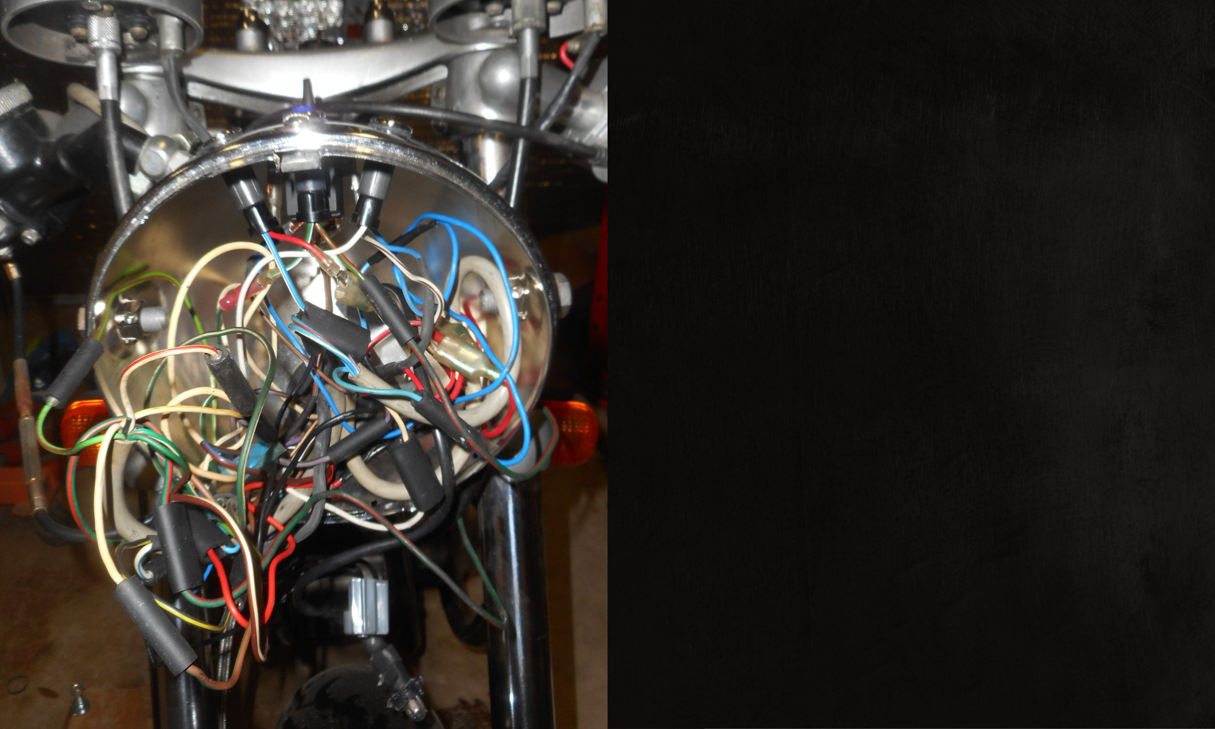
No, it was not pretty. And beyond its being “positive earth,” it was a giant mess of tangled wires and bullet connectors, in no small part because 50 years of American mechanics (who didn’t understand that ground was not the negative battery terminal) had left it in less than pristine shape. It really was a wiring (and wiring diagnosis) nightmare, and it had to go.

The jumble of wires inside the headlight bucket before we started the cleanup exercise.
What We Did: The Microprocessor and Transistor Circuits
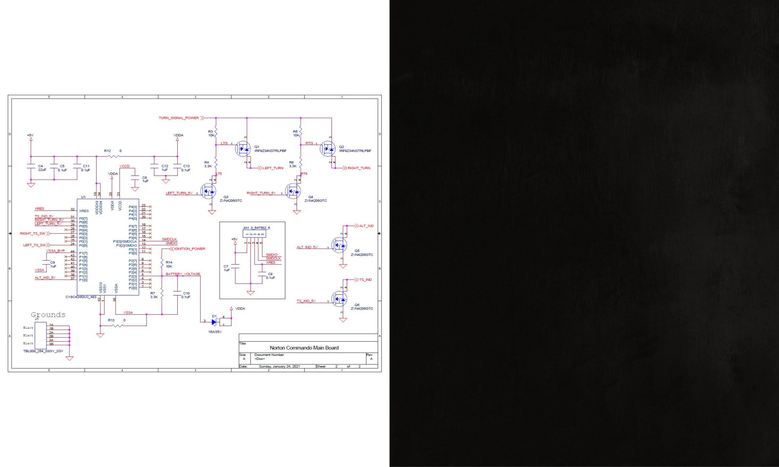
Yes, it’s overkill, but it’s actually less expensive to manufacture than just about anything else. A microprocessor times the flashing of the turn indicators and measures battery voltage to determine if it’s time to turn on the charging circuit warning light. Transistors (in this case, power MOSFET’s) do the business of turning the LED’s on. For the indicator lights on the headlight housing, n-channel FET’s work, since we provide the 12V to the top sides of the LED lights and can turn them on by pulling their bottom ends low. For the turn lights themselves (the bright ones people see), the bike’s frame is connected to the battery’s negative terminal once we’ve flipped “positive earth” to the more normal “negative ground” state of affairs. So the LED has to be driven from a p-channel FET on the high side, with a cascaded n-channel FET on the low side stepping up the 5V (on which the microprocessor runs) to the 12V the LED lamp expects to see.

The ARM Cortex-M0 embedded controller and transistor light driving circuits on the modern board.
What We Did: System on Chip ARM-Core Processor Design
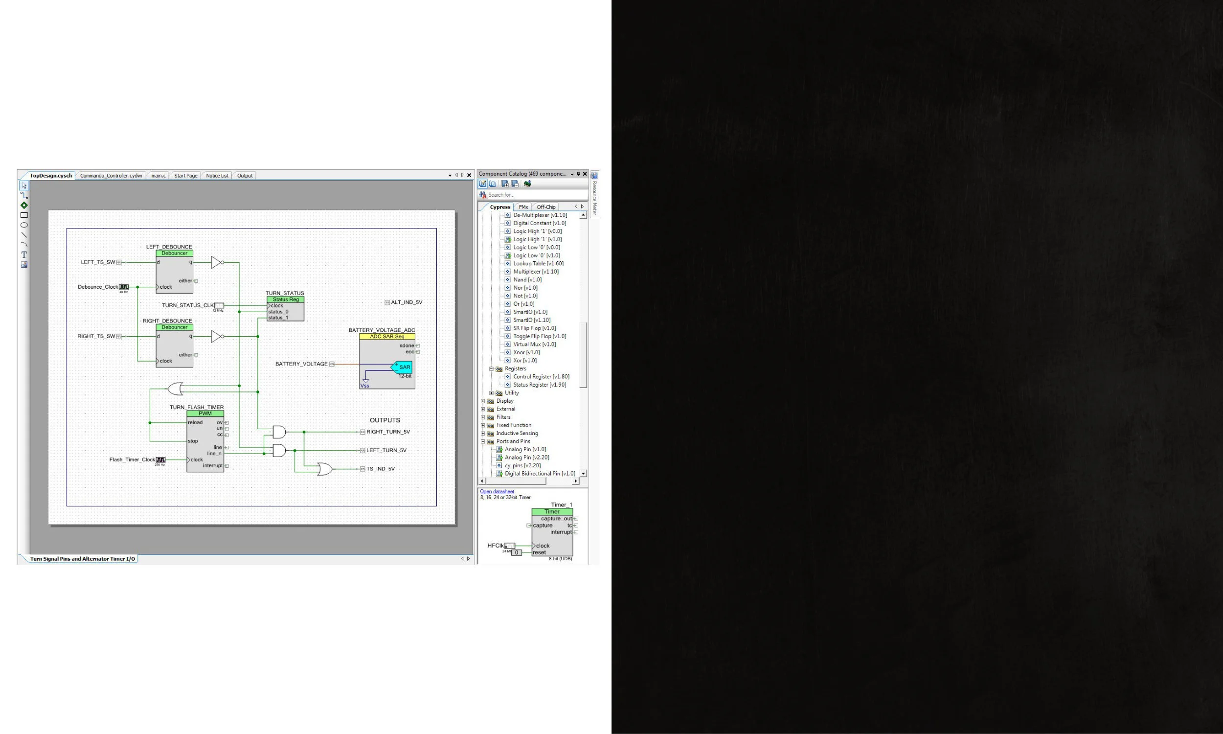
At the heart of the design was a Cypress/Infineon PSoC4 (Fourth Generation Programmable System on Chip) ARM Cortex-A0 microcontroller chip. But because the PLD logic surrounding the ARM core was programmable under our control, it fell to us to implement the schematics and write the HDL code to put all the flops on the silicon in the places required to make the turn indicators flash and do the analog-to-digital conversion to check on battery/alternator health.

The programmable logic array inside the embedded controller chip — loaded with turn signal and battery monitoring circuits.
What We Did: Figuring out the Mechanicals to get a PCB inside a Headlight “Bucket”
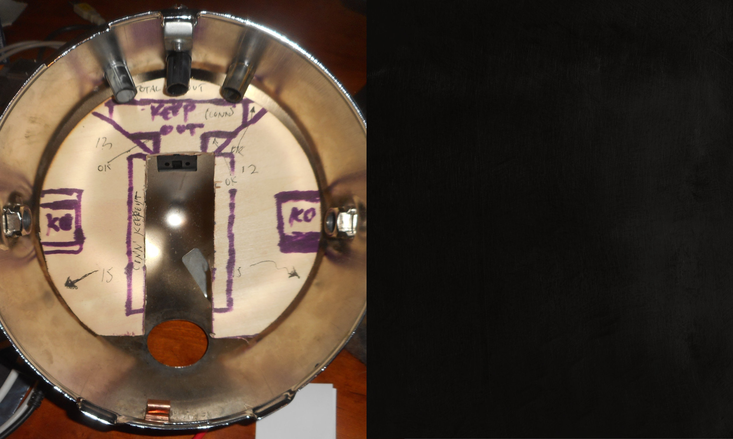
Space was limited, and whatever we did had to be concealed so as not to diminish in any way the classic lines of the bike.

A piece of balsa wood marked with a Sharpie pen was a handy tool for checking mechanical clearances on all components on the proposed printed circuit board (PCB).
What We Did: Developing the PCB Outline
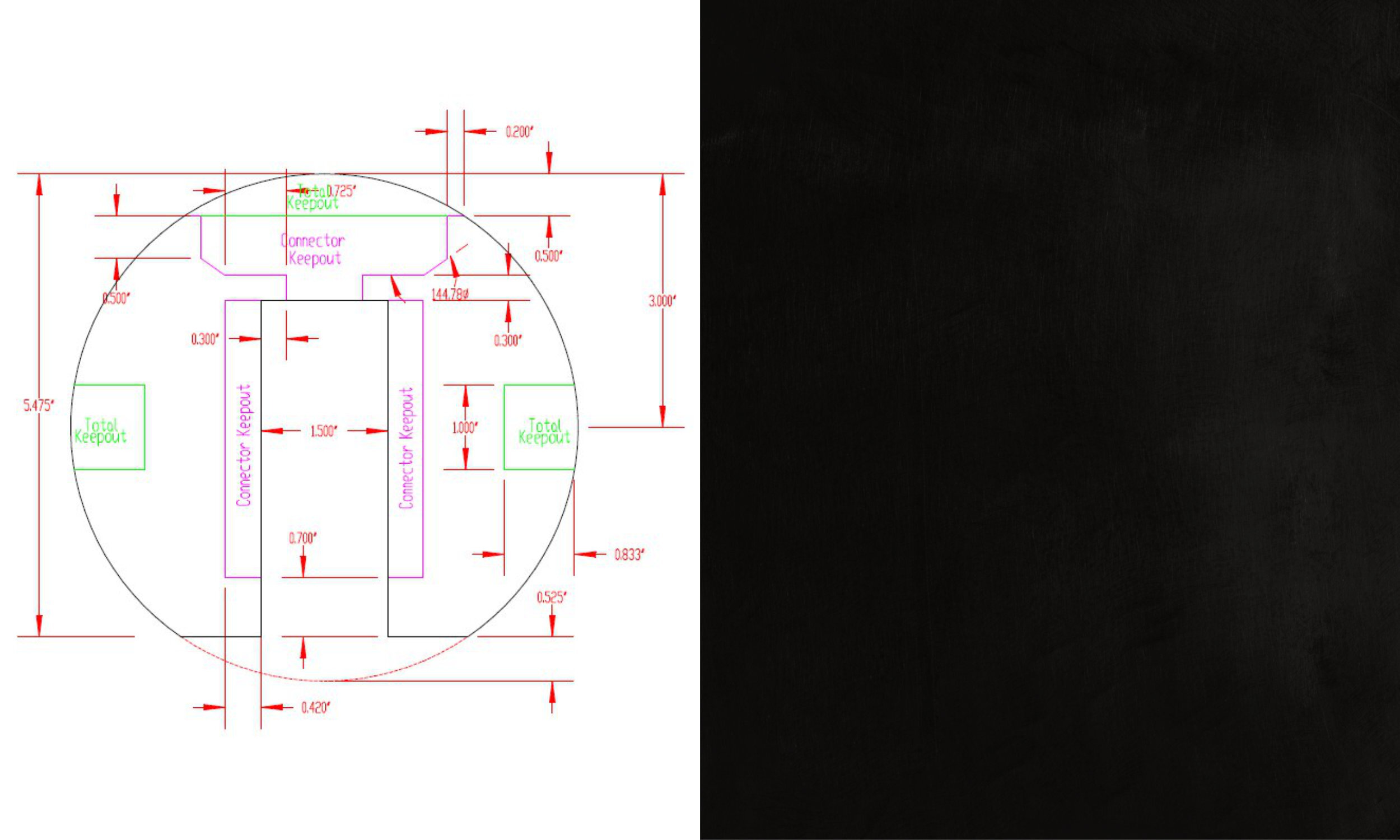
Once we had a balsa wood mockup of the desired PCB, it was time to get that into DXF form as a mechanical drawing we could lay out in our circuit board layout CAD program.

Dimensions taken off the Balsa wood PCB mockup were fed into a mechanical CAD program capable of exporting PCB outline information to the PCB layout program.
What We Did: PCB Layout
Armed with a DXF file derived from our balsa wood mockup, we produced a design for a PCB that would fit inside the headlight bucket.
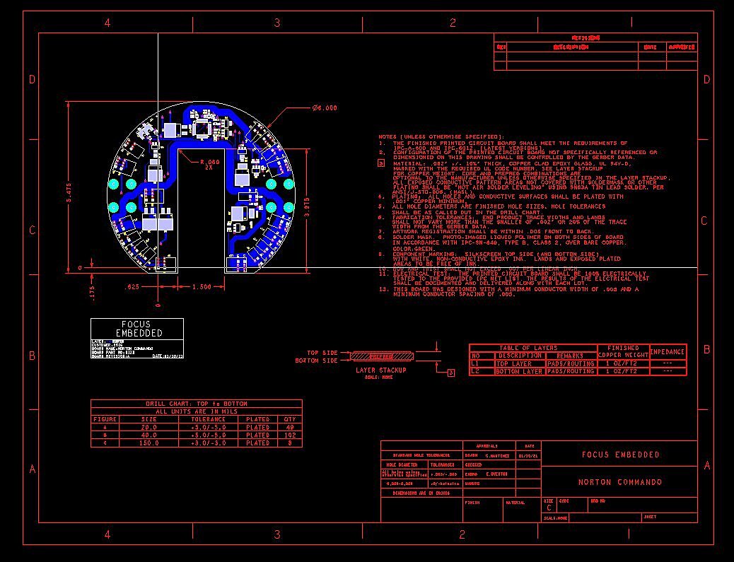
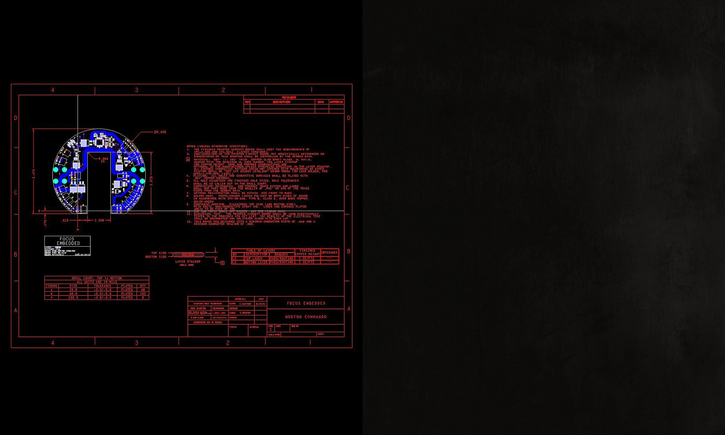
Photoplot (“Gerber data“) files for generating a printed circuit board (PCB) to mount inside the headlight bucket.
What We Did: Checking Fit and Headlamp Clearance
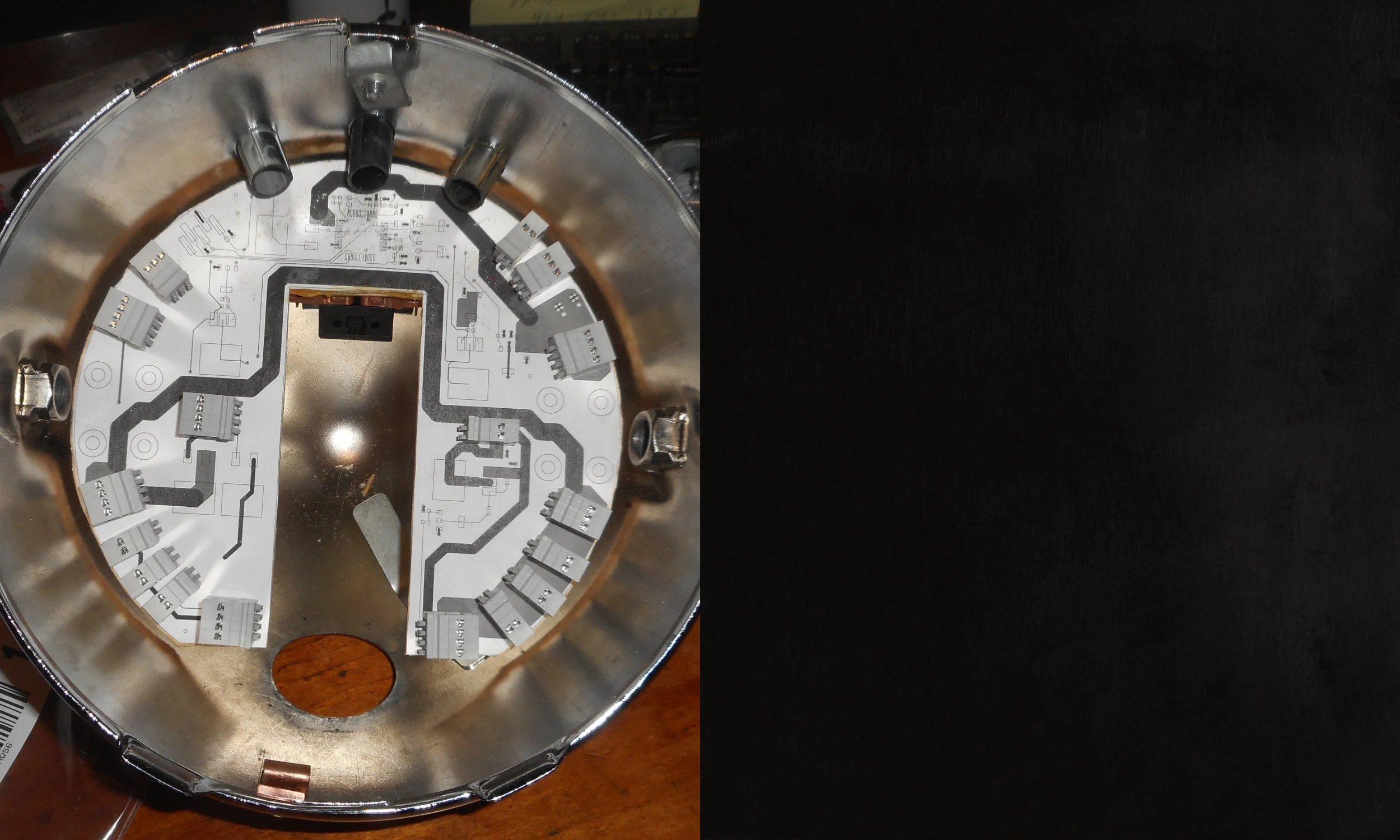
Once we had a complete PCB layout, before we went to fabrication with it, we printed a 1:1 paper copy, mounted it to balsa wood, and checked all clearances — particularly the vertical clearances for the various connectors, since those were the tallest components and were most likely to interfere with the back side of the parabolically shaped headlamp reflector.

Final balsa wood mockup of the PCB for one last mechanical clearance check before we sent the photoplots off for fabrication at one of our circuit board maker partners.
The End Result: Neat Wiring with Reliable Modern Connectors
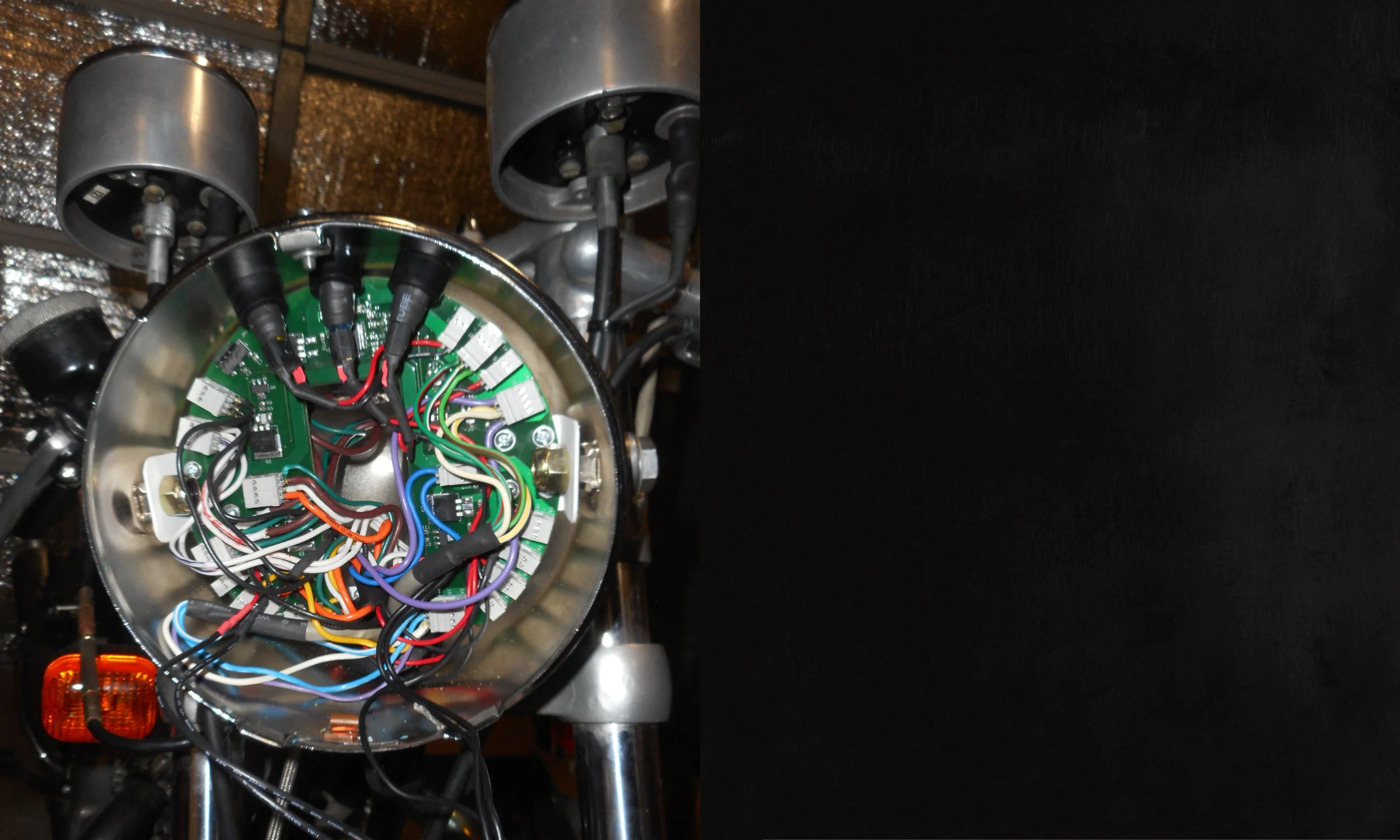
The proof was in the pudding. A reliable negative-grounded, transistorized, microprocessor-controlled pudding.

When it all came together — just before going back out on the road.