Smart Oil Pipeline Flow Valve
Client:
Flowserve
Competencies:
Basic Physics (Classical Electrodynamics)
Capacitive Measurement System Design
Embedded Firmware Design
A Smart Valve for Oil Pipelines
An oilfield is covered with pipe to get the oil from the wells to where it can be stored and shipped. The trick is to use as little pipe as you can in order to move as much oil as you can extract from the wells. And that means deploying pipe intelligently and then monitoring which pipes are actually carrying oil at the time.
Our customer hit on the idea of making the valves smart enough to know when a pipe was dry (and therefore available to carry oil) by using a capacitance-based sensor to detect the presence of liquid. With no moving parts (such as a float switch) that could be crudded up by crude oil, a “CapSense” design could be made far more reliable.
The catch is that most CapSense devices are used in things such as touch screens or touchpads on appliances, where they’re detecting the presence of a finger. A finger, being mostly water, has a dielectric constant (dimensionless) of about 80. Most petrochemicals have a dielectric constant of between 2-4. So a massive re-tuning of the detection circuitry was automatically in order.
Additionally, nobody had yet done the physics to determine the optimal shape of the center electrode and sleeve. So the capacitor itself (whose dielectric — either air or oil) wasn’t optimally designed. That was about the time we cracked open a well-worn copy of Halliday and Resnick and got down to business.
The end result? An inexpensive and highly reliable oil sensor inside a valve body. No moving parts, nothing mechanical to break, and no temperature sensitivity.
What We Did: Our Own Machining
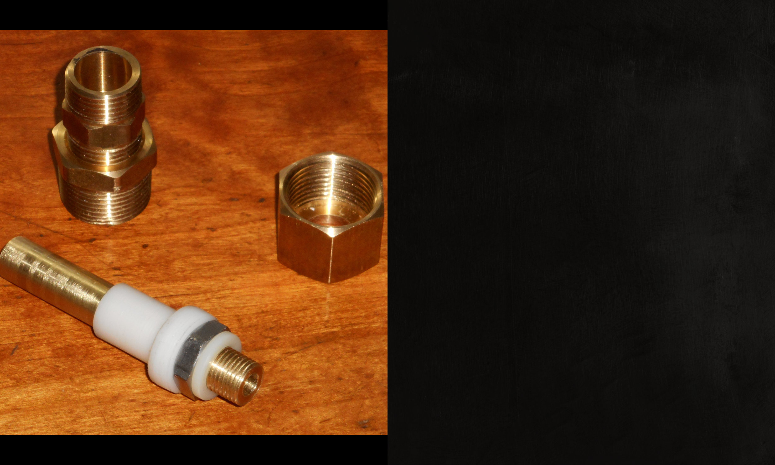
Yes, we’re an electrical design shop. But that doesn’t mean we don’t have a small lathe and mill at our disposal and can’t make a few parts when we have to.
In this case we had to, since we were starting from scratch with the capacitor geometry. A few trips to the local hardware store and metal supplier got us some raw stock (brass, mostly, since it machines quickly and easily) and a few NPT fittings from the plumbing aisle with which we could make the exact size of center electrode and outer sleeve to create exactly the size and shape of capacitor we needed.

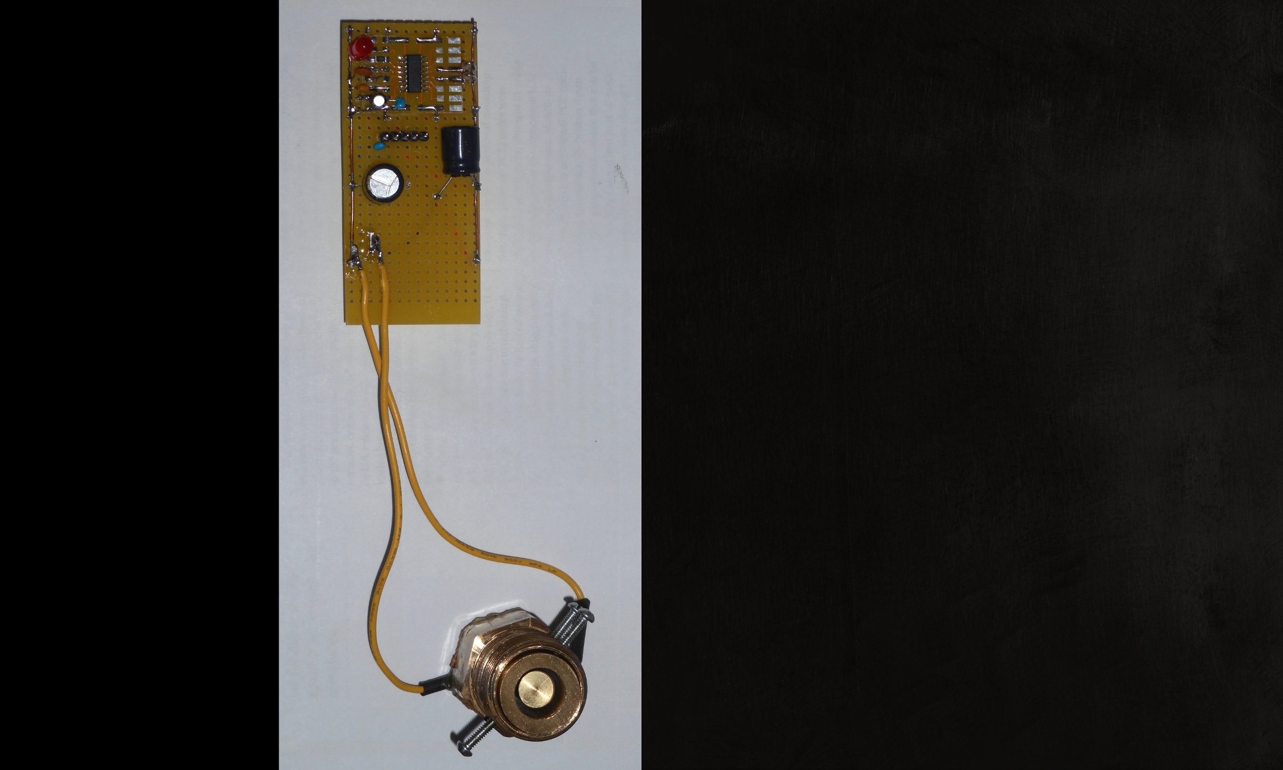
What We Did: A Prototype for Testing
Armed with a workable capacitor, we connected a Cypress/Infineon PSoC4 processor with a “Capsense” component built into it. And with that setup, we began the process of tuning the excitation signal and the recovery circuits that measure capacitance.

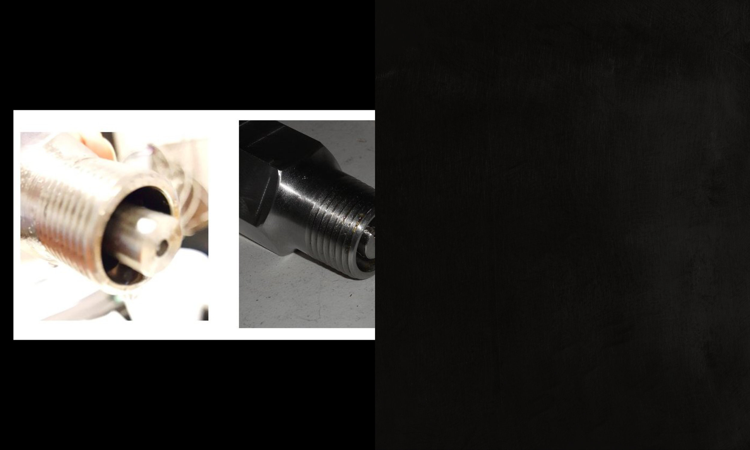
What We Did: The Final Capacitor Design
At left in the composite image below is the capacitor as it was originally designed by our customer. At right is how we eventually specified that it be made — with a smaller gap between the core and the outer (sleeve) electrode and without the center electrode protruding beyond the end of the sleeve. This kept electric field lines short and kept them from bending in too many strange ways at the end.

What We Did: Tuning the Capacitance Sensor
Once we had a capacitor design that made sense, we had to do some pretty drastic re-tuning of sensor code (that generated a signal for excitation and recovered it to measure the attenuation due to impedance) that was originally designed to sense water (dielectric = 80), not crude oil (dielectric = ~3). Water has a strong dipole moment, and it’s therefore quite easy to detect when it’s the dielectric substance in the center of a capacitor. (This is what makes a finger so easy to see on a touch screen, since the human body is mostly water.) Petrochemicals are mostly long-chain molecules made of carbon and hydrogen, and they have almost no dipole moment at all.

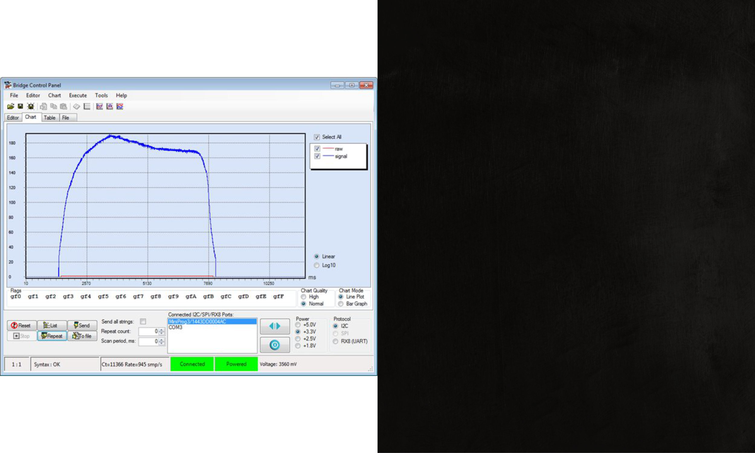
Watching it in Action.
With everything suitably tuned, we were able to immerse the end of the sensor electrode in motor oil and see the detector light up.
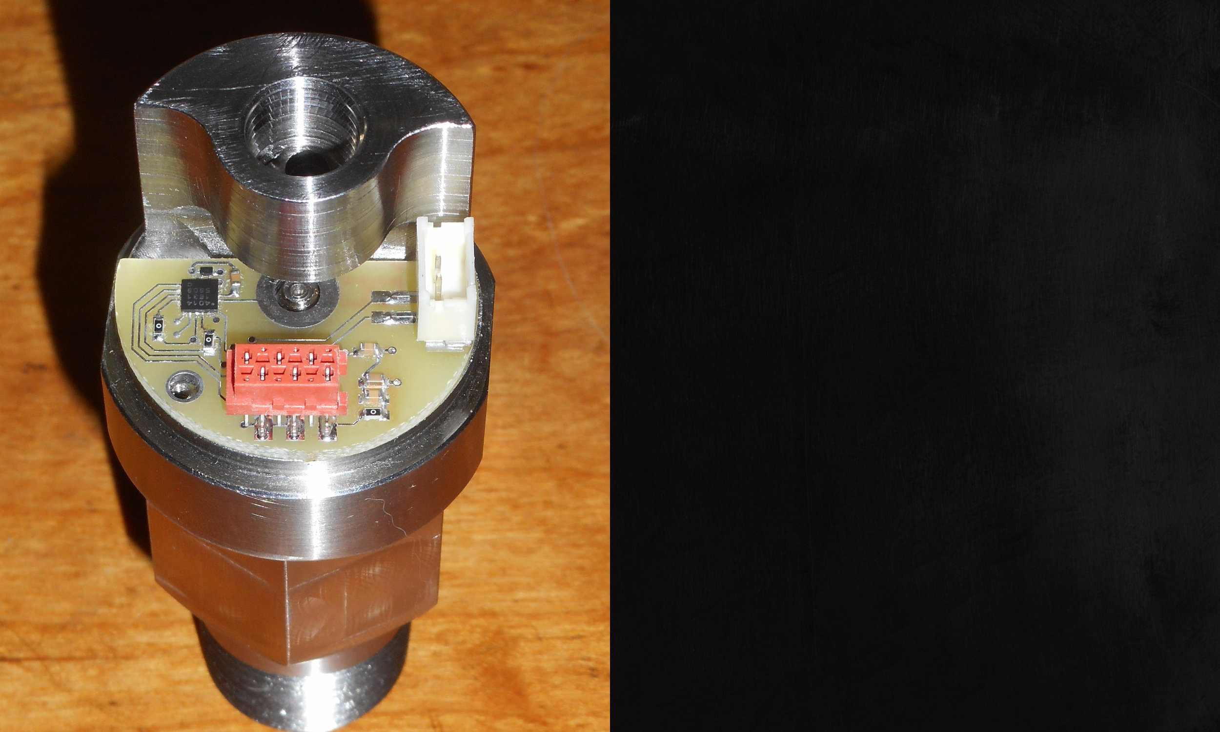
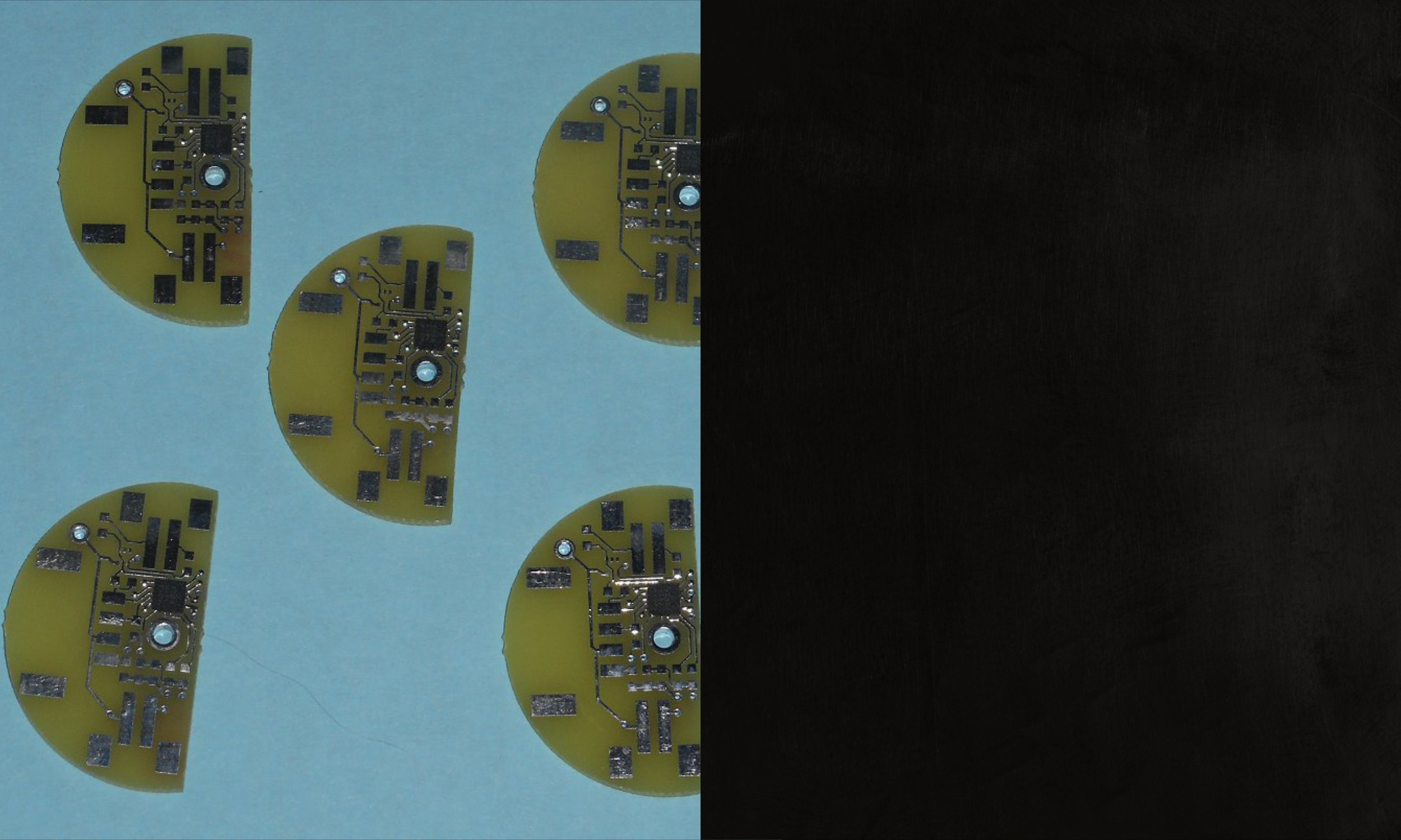
Putting it all on a PCB
The last step was to fabricate a PCB in the half-moon shape that would fit inside the valve body. At the center of the half circle (the dead center of the valve) we placed a plated hole into which a screw was inserted to hold the board to the center electrode and form one connection to the capacitor. At the board’s edge, a second hole took a smaller screw that formed the circuit connection to the outer electrode. These five boards were hand-assembled prototypes, but once they were field tested and shown to work, we sent out full panelized Gerber data for boards with a silksceen and soldermask.
Low-cost prototype PCB’s for testing the overall design. In production these board had silkscreen and soldermask and were laid up a few hundred on a panel.